Ray tracer for those who skipped the math class
There is a strong belief that every programmer in their life must write a ray tracer. But unlike many other programming exercises, ray tracers often require some mathematical background. Even those who were good at math back in the school days - might hesitate to dust off the rust from their brains to only write a pointless (although, very cool) toy program.
For those who don’t know what I’m talking about - ray tracer is an app that renders 3-dimensional objects, lights, reflections, all done by tracing the rays of light through the world of objects, shapes, and materials. There is even a popular challenge - writing a “business card” ray tracer, a small one, with the features you like, implemented in your own language of choice.
So let’s walk through it together, there will be almost no mathematical formulas, but there will be illustrations and around 100 lines of primitive code. No prior knowledge of computer graphics or OpenGL is required.
Vectors
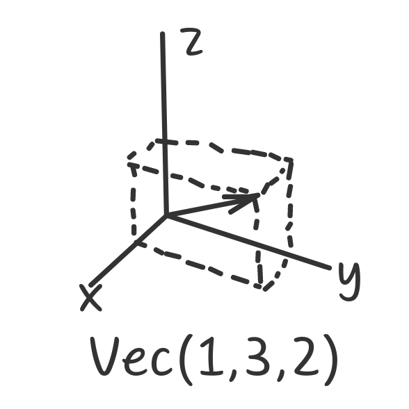
The core of the ray tracer is vector arithmetics. From the programming perspective, a 3-dimensional vector is just a tuple of 3 elements - x, y, and z. It is often represented visually as an arrow, which might be confusing, because vectors in our ray tracer serve multiple purposes - they describe points in 3D space, they describe directions, they even might describe RGB colors or material properties, but we’ll restrain from this.
struct Vec {
  float x, y, z;
  Vec(float vx, float vy, float vz) : x(vx), y(vy), z(vz) {}
};

Vec v = Vec(1, 3, 2); // The vector on the picture above
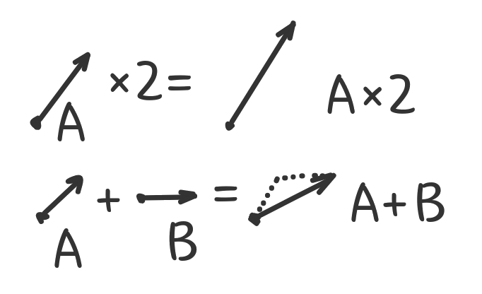
What can we do with vectors? The easiest operation is multiplication by a number. You can think of it as “making the vector n times longer”. In programming terms for vector A that would mean: “multiply A.x, A.y and A.z by n”.
Adding two vectors A and B is also not that hard. Imagine putting them one after another and connecting the start of the first vector with the end of the second one. Or, in programming terms: “add A.x with B.x, add A.y with B.y, add A.z with B.z”.
struct Vec {
  float x, y, z;
  Vec(float vx, float vy, float vz) : x(vx), y(vy), z(vz) {}
  Vec operator+(Vec vec) { return {x + vec.x, y + vec.y, z + vec.z}; }
  Vec operator-(Vec vec) { return {x - vec.x, y - vec.y, z - vec.z}; }
  Vec operator*(float n) { return {x * n, y * n, z * n}; }
};
Minus operation A-B is no different from adding two vectors (it’s the same as A×(B*(-1))), but can make the code more readable.
Three more operations – and we have enough knowledge about vectors to build a ray tracer.
Dot product. It tells you what amount of one vector goes in the direction of another. Or a “projection” of the first vector onto the second. The result is not a vector, but a single number, a length of the “projection” multiplied by the length of the second vector. The formula is much simpler than it sounds, just multiply all the coordinates in pairs and add them:
// dot product
float operator%(Vec vec) { return x * vec.x + y * vec.y + z * vec.z; }
Now, what would be the dot product of vector on itself? Right, squared length (magnitude) of the vector. So we can now add a method to calculate vector own length:
float length() { return sqrtf(*this % *this); }
Finally, we can divide the vector by its length and get a vector with the same “direction” but the length of 1, known as a unit vector:
Vec unit() { return Vec(x, y, z) * (1 / this->length()); }
And we are done with vectors.
Spheres
Vectors are only the underlying math. On the high level we will be operating with objects in a three-dimensional world. To keep things simple, all objects will be spheres. It would be still possible to implement “walls” using the spheres of a very large radius.
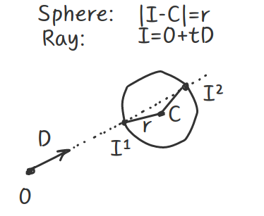
A sphere is typically defined by a center C and a radius r. The only thing we need to do with the spheres is to find how they intersect with the given ray of light.
Rays of light would be represented by a couple of vectors: the point of origin (where xyz would be the coordinates) and the direction (where xyz would be the unit vector pointing the ray).
struct Sphere {
  Vec center;
  float radius;
  float intersect(Vec origin, Vec direction) {
    // Return distance from the ray's origin to the intersection, or NAN if there is none.
  }
};
Ray-sphere intersection requires doing some math with some variable substitution. If this get boring - feel free to skip to the final formula or code, but I’ll try to keep things simple.
A sphere, by definition, is a set of points that are all at the same distance r from the center C. In other words, any point S belonging to the sphere satisfies the following equation:
(S - C).length() = r
// or, squared, using dot product:
(S - C)·(S - C) = r²
Ray, as mentioned above is a set of points located along the same line, so linear equation fits here:
Ray = O + tD, where "t" increases the points get further from the origin of the ray.
So, if the intersection point I belongs to both, the sphere and the ray, it should satisfy:
((O + tD) - C)·((O - tD) - C) = r²
// ...or
((O - C) + tD)·((O - C) - tD) = r²
// introduce some helper alias:
let P = O - C
(P + tD)·(P - tD) = r²
// ...explanded:
t²(D·D) + 2t(P·D) + P·P - r² = 0
// Looks like a square equation (ax²+bx+c=0)!
// ...where coefficients are:
let a = D·D
let b = 2(P·D)
let c = P·P-r²
// And the solution is, as in a typical square equation:
t = (-b ± √(b²-4ac)) / 2a
The ± sign there means that (assuming that a≠0) there would be two intersection points, one at the “front” of the sphere and another at the “back” after the ray “pierced” the sphere.
Now, maybe source code would be more eloquent:
float intersect(Vec origin, Vec direction) {
  // p = O-C
  Vec p = origin - this->center;
  // a = D·D
  float a = direction % direction;
  // b = 2(P·D)
  float b = 2 * (p % direction);
  // c = P·P - r²
  float c = (p % p) - (this->radius * this->radius);
  // d = b²-4ac
  float d = b * b - 4 * a * c;
  if (d < 0) {
    // Negative square? There is no intersection!
    return NAN;
  }
  float sqd = sqrtf(d);
  // First try the closest point on ray
  float distance = (-b - sqd) / (2.f * a);
  if (distance > .1f) {
    return distance;
  }
  // If not - try the one further away (i.e. ray originates inside a large sphere and hits the back)
  distance = (-b + sqd) / (2.f * a);
  if (distance > .1f) {
    return distance;
  }
  // No intersection!
  return NAN;
}
Keep in mind that it’s not the only approach to find intersection points. There is also a so-called “geometric solution”, but I leave it to the reader to google up.
We did the hardest part of the ray tracer. Now we need to construct the world and apply this method to all the spheres there.
World
To leave our ray tracer uncomplicated, our world would consist of two collections, spheres and lights. We also introduce one additional field to the Sphere type - color. Here I will keep in monochrome, not only it looks more dramatic, but also simplifies the calculations a bit and leaves you some space for improvement:
struct Sphere {
  ...
  float color; // 0 = black, 1 = white
  ...
};

struct World {
  std::vector<Sphere> spheres;
  std::vector<Sphere> lights;
};

World world = {
  { // spheres
    {{0, -1000, 0}, 0.001, 1000}, // large dark plane, the "ground"
    {{-2, 1, -2}, 1, 1}, // white sphere on the left
    {{0, 1, 0}, 0.5, 1}, // grey sphere in the center
    {{2, 1, -1}, 0.1, 1}, // dark sphere on the right
  },
  { // three directional lights of various brightness
    {{0, 100, 0}, .4, 0},
    {{100, 100, 200}, .5, 0},
    {{-100, 300, 100}, .1, 0},
  },
};
Bear with me, we are only two functions away from the end result.
We need to render the scene somehow. Again, I won’t talk about graphics formats or UI frameworks here, so we will render it using good old ASCII graphics. We need to set the point of view, say {0,1,5} - in the middle, slightly above the ground, in front of the spheres. Then for each “pixel” we should calculate the ray direction unit vector, that would originate from the point-of-view and hit the pixel as if it was on some invisible screen between the point-of-view and the world. If the screen is W×H pixels and put H pixels away from the point-of-view, the could iterate the rays like:
void render(World world, int width, int height) {
  for (int y = 0; y < height; y++) {
    for (int x = 0; x < width; x++) {
      Vec direction = Vec(x - width / 2, height / 2 - y, -height).unit();
      // c would be the color of the pixel
      float c = trace(world, {0, 1, 5}, direction);
      // find the suitable ASCII symbol "density" from 0 to 10
      char pixel = " .:-=+*#%@$"[(int)(c * 10)];
      std::cout << pixel << pixel;
    }
    std::cout << std::endl;
  }
}
Tracing rays
The final and the most interesting step, implementing the trace() function. That’s the most annoying thing about ray tracers - you can only see them working (or not working) after all the core parts are implemented. So, please be patient.
First, it should loop over all the spheres and find the nearest intersection of them all (if one sphere appears in front of the other - it would be the nearest ray intersection).
Here’s our first attempt:
float trace(World world, Vec origin, Vec direction) {
  int index = -1;       // nearest sphere index
  float distance = NAN; // nearest sphere distance

  for (int i = 0; i < world.spheres.size(); ++i) {
    // Loop over every sphere, find nearest non-NAN intersection
    float d = world.spheres[i].intersect(origin, direction);
    if (!std::isnan(d) && (index < 0 || d < distance)) {
      distance = d;
      index = i;
    }
  }
  if (h < 0) {
    return 0; // If no intersection: return black color
  }
  // If there is a sphere - return white color
  return 1;
}
And, here are our first results!
                                      $$$$$$
                                  $$$$$$$$$$$$$$        $$$$$$
                      $$$$$$$$  $$$$$$$$$$$$$$$$$$  $$$$$$$$$$$$
                    $$$$$$$$$$$$$$$$$$$$$$$$$$$$$$$$$$$$$$$$$$$$$$
                    $$$$$$$$$$$$$$$$$$$$$$$$$$$$$$$$$$$$$$$$$$$$$$
                  $$$$$$$$$$$$$$$$$$$$$$$$$$$$$$$$$$$$$$$$$$$$$$$$$$
                    $$$$$$$$$$$$$$$$$$$$$$$$$$$$$$$$$$$$$$$$$$$$$$
$$$$$$$$$$$$$$$$$$$$$$$$$$$$$$$$$$$$$$$$$$$$$$$$$$$$$$$$$$$$$$$$$$$$$$$$$$$$$$$$
$$$$$$$$$$$$$$$$$$$$$$$$$$$$$$$$$$$$$$$$$$$$$$$$$$$$$$$$$$$$$$$$$$$$$$$$$$$$$$$$
$$$$$$$$$$$$$$$$$$$$$$$$$$$$$$$$$$$$$$$$$$$$$$$$$$$$$$$$$$$$$$$$$$$$$$$$$$$$$$$$
$$$$$$$$$$$$$$$$$$$$$$$$$$$$$$$$$$$$$$$$$$$$$$$$$$$$$$$$$$$$$$$$$$$$$$$$$$$$$$$$
$$$$$$$$$$$$$$$$$$$$$$$$$$$$$$$$$$$$$$$$$$$$$$$$$$$$$$$$$$$$$$$$$$$$$$$$$$$$$$$$
$$$$$$$$$$$$$$$$$$$$$$$$$$$$$$$$$$$$$$$$$$$$$$$$$$$$$$$$$$$$$$$$$$$$$$$$$$$$$$$$
$$$$$$$$$$$$$$$$$$$$$$$$$$$$$$$$$$$$$$$$$$$$$$$$$$$$$$$$$$$$$$$$$$$$$$$$$$$$$$$$
$$$$$$$$$$$$$$$$$$$$$$$$$$$$$$$$$$$$$$$$$$$$$$$$$$$$$$$$$$$$$$$$$$$$$$$$$$$$$$$$
$$$$$$$$$$$$$$$$$$$$$$$$$$$$$$$$$$$$$$$$$$$$$$$$$$$$$$$$$$$$$$$$$$$$$$$$$$$$$$$$
$$$$$$$$$$$$$$$$$$$$$$$$$$$$$$$$$$$$$$$$$$$$$$$$$$$$$$$$$$$$$$$$$$$$$$$$$$$$$$$$
$$$$$$$$$$$$$$$$$$$$$$$$$$$$$$$$$$$$$$$$$$$$$$$$$$$$$$$$$$$$$$$$$$$$$$$$$$$$$$$$
Impressive, aren’t they? Well, some people see a lot of dollars here, but I see three spheres put on top of the large “ground” sphere. All painted white. The pixels that do not belong to the spheres are black. Baby steps.
Now, let’s paint our spheres the right color: return world.spheres[h].color instead of return 1:
                                      ++++++
                                  ++++++++++++++        ......
                      $$$$$$$$  ++++++++++++++++++  ............
                    $$$$$$$$$$$$++++++++++++++++++................
                    $$$$$$$$$$++++++++++++++++++++++..............
                  $$$$$$$$$$$$++++++++++++++++++++++................
                    $$$$$$$$$$++++++++++++++++++++++..............
                    $$$$$$$$$$$$++++++++++++++++++................
                      $$$$$$$$  ++++++++++++++++++  ............
                                  ++++++++++++++        ......
                                      ++++++
Much better! White on the left, grey in the middle, dark on the right. The ground sphere is all black. So is the sky, but that’s a different topic.
Let’s trace the lights. We should iterate through all the lights in the scene, for each light - iterate through all spheres, and… do what? For each light we need to calculate its contributions:
- Find a point of intersection P for the point-of-view ray and the nearest sphere.
- Find the normal N to that point of intersection:
(P-C).unit(). - Find direction D from each light origin L to the point of intersection P:
(L-P).unit() - Find if there any shadowing sphere, that intersects the ray originating at P with direction D.
- If there is shadow - return a dimmed color of the sphere (return 10% of the original sphere brightness)
- If there is no shadow and the point P is not hidden from light - find out the contribution and combine it with the current pixel color.
In C++ that would be:
float trace(World world, Vec origin, Vec direction) {
  ...
  // we have `distance` to the nearest sphere intersecting the point-of-view ray
  ...
  Vec p = origin + direction * distance;
  Vec n = (p - world.spheres[h].center).unit();
  float c = world.spheres[h].color * 0.1f;
  for (auto light : world.lights) {
    Vec l = (light.center - p).unit();
    int shadow = 0;
    for (auto sphere : world.spheres) {
      if (!std::isnan(sphere.intersect(p, l))) {
        shadow = 1;
      }
    }
    if (!shadow) {
      // Try:
      return world.spheres[h].color;
      // Or try:
      return world.spheres[h].color * light.color;
    }
  }
  return c;
}
Whether we return just sphere color, or sphere color adjusted by the light - we still get bad results, looking nothing like 3D. Light contribution depends a lot on the angle between the light and the sphere normal. If the angle is almost 90° - the light beams brightly, if the angle is close to zero - the light ray looks dimmer. This is where vector dot point operator helps us:
float diffuse = std::max(0.f, (l % n) * 0.7f);
float specular = powf(fmax(0.f, (l % n)), 70.f) * 0.4f;
c = c + world.spheres[h].color * light.color * diffuse + specular;
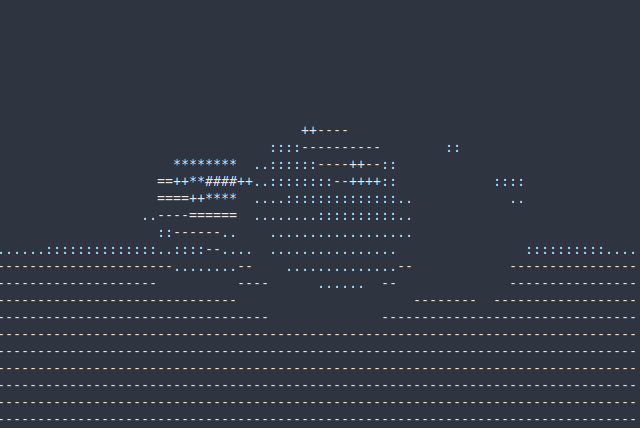
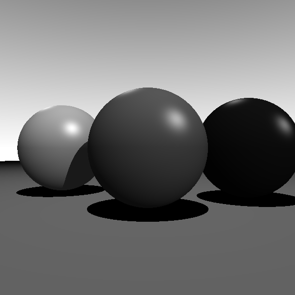
Coefficients are purely random, but the picture looks very different now in my terminal:
Bonus
There is a special old graphics format, that people seem to use exclusively in ray tracers these days - PGM/PNM/PPM. It’s a text format where each pixel is store as a decimal number. Now, as we are comfortable with ray tracer internals - we can play around with graphics output:
// Very similar to our render() function above, but export PGM format
// Each pixel is a number, where 0 is black and 255 is white.
void render_pgm(World world, std::string filename, int width, int height) {
  std::ofstream f(filename);
  f << "P2" << std::endl << width << " " << height << " 255" << std::endl;
  for (int y = 0; y < height; y++) {
    for (int x = 0; x < width; x++) {
      float c = trace(world, {0, 1, 5},
                      Vec(x - width / 2, height / 2 - y, -height).unit());
      f << ((int)(c * 255)) << " ";
    }
  }
}
Another little trick to add is the sky. Rather than returning constant black - we can return a grey gradient, that gets lighter as it goes down:
The full code is available on GitHub: https://gist.github.com/zserge/d22d7b226dd9989f00b1ff8d16e01e0c
Ray tracer itself is ~80 lines of code, rendering functions are ~10 lines each - it would be easy to read and understand.
We can also experiment with stereo pictures, rendering the same scene from slightly different points of view. Or add RGB colors to the objects. Or cast shadows differently, but casting a few random rays and filtering the results. Or add materials with different diffusion/reflection and other properties. Or handle more shapes - cylinders, cones, cubes. I hope I shed some light on the basics and you would be able to write your own, much more powerful and beautiful ray tracer!
I hope you’ve enjoyed this article. You can follow – and contribute to – on Github, Mastodon, Twitter or subscribe via rss.
Apr 22, 2021
See also: A "Better C" Benchmark and more.
